Electrical / Motors / Wound Field Synchronous Machine (WFSM)
Description
Wound Field Synchronous Machine (WFSM)
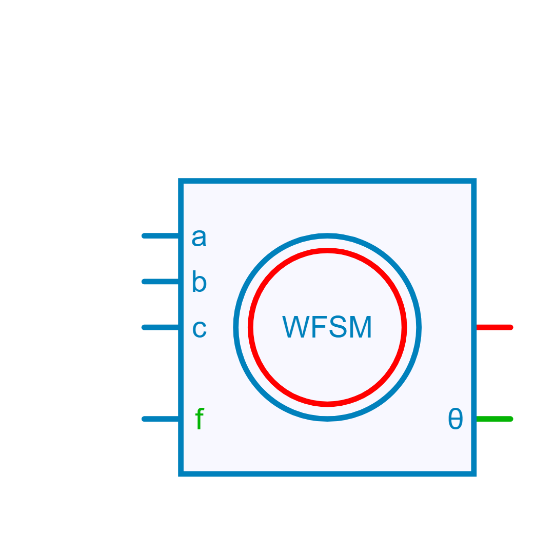
Model of a three-phase Wound Field Synchronous Machine (WFSM). In motor operation torque and speed have the same sign. Rotor Angle is defined as the angle between the a-phase and the d-axis. Stator winding is star connected in this model. To access the neutral point pin, check the "Neutral Point" checkbox in the properties menu.
Electrical model and equations
Phase inductances (L_{aa}, L_{ab}, L_{ac},..., L_{cc}) are calculated from the stator inductance in the synchronous reference frame (L_{d}, L_{q}) defined in the property panel as the incremental inductance.
Field inductances (L_{amf}, L_{bmf}, L_{cmf} and L_{f}) are calculated from the field circuit self- and mututal- inductance (L_{f}, M_{fd}).
Electromechanical equations
Electro-magnetic torque:
where \phi_d = L_d i_d + 2/3 * M_{fd} * i_f and \phi_q = L_q i_q
Mechanical rotational speed \Omega:
Library
Electrical > Motors
Parameters
| Property | Display Name | Parameter Type | Description |
|---|---|---|---|
| Rs | Rs - Stator Resistance [Ohm] | DoubleParameter | Stator Winding Resistance [Ohm] |
| Rf | Rf - Rotor Resistance [Ohm] | DoubleParameter | Stator Winding Resistance [Ohm] |
| Ld | Ld - Direct Axis Inductance [H] | DoubleMatrixParameter | Direct Axis Inductance [H] |
| Lq | Lq - Quadratic Axis Inductance [H] | DoubleMatrixParameter | Quadratic Axis Inductance [H] |
| J | J - Rotor Inertia [kg.m²] | DoubleParameter | Rotor Inertia [kg.m²] |
| B | B - Rotor Friction Coefficient [N.m/(rad/s)] | DoubleParameter | Rotor Friction Coefficient [N.m/(rad/s)] |
| InitialSpeed | Rotor Initial Speed [rad/s] | DoubleParameter | Rotor initial speed [ rad/s] |
| InitialCurrent | Initial Current [A] | DoubleArrayParameter | Initial Current Vector [IA IB IC] |
| NPP | NPP - Poles pairs | IntParameter | Number of pole pairs |
| ExposeNeutralPoint | Neutral Point | BoolParameter | Expose Neutral Point (Boolean) |
| Use2DTable | use 2D inductance table | BoolParameter | Use 2D inductance table (Boolean) |
| Lf | Lf - Field Circuit Self-Inductance [H] | DoubleMatrixParameter | Field Circuit Inductance [H] |
| Mfd | Mfd - Field Circuit Mutual-Inductance [H] | DoubleMatrixParameter | Field Circuit Inductance [H] |
Pins
| Property | Pin Name | Type | Description |
|---|---|---|---|
| Pin_A | A | Electrical | Phase A (Electrical) |
| Pin_B | B | Electrical | Phase B (Electrical) |
| Pin_C | C | Electrical | Phase C (Electrical) |
| Pin_F | F | Electrical | Field (Electrical) |
| Pin_R | R | RotationalMechanical | Rotor (Rotational Mechanical) |
| Pin_Angle | Angle | ControlOut | Rotor Angle in radians, electrical angle (Control) |
Default Size
| Width | Height |
|---|---|
| 8 | 8 |