Electrical / Motors / Synchronous Reluctance Machine (SynRM)
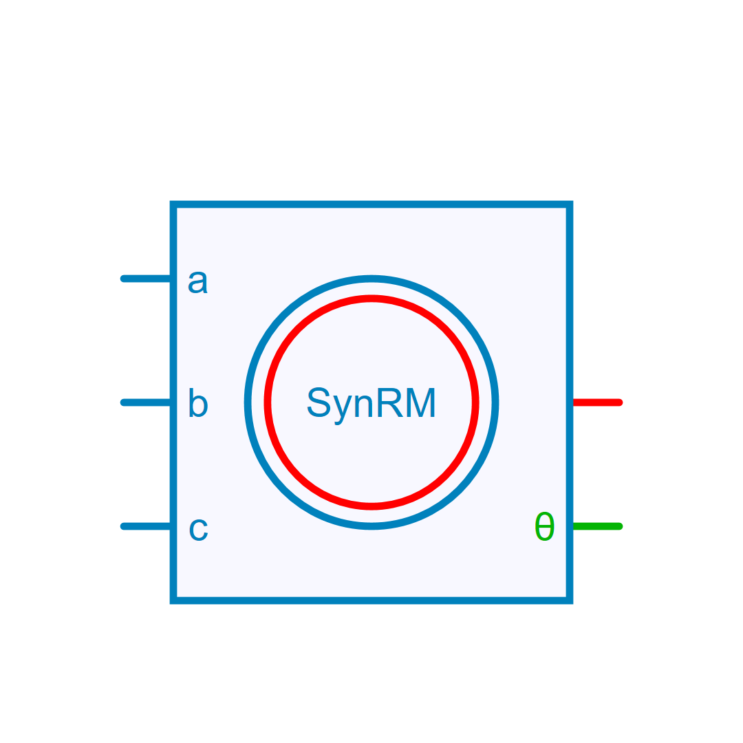
Description
Synchronous Reluctance Machine (SynRM)
Model of a three-phase Synchronous Reluctance Machine (SynRM). In motor operation torque and speed have the same sign. Rotor Angle is defined as an angle between the a-phase magnetic axis and the d-axis.In this model, the saturation can be modeled using a piecewise linear approximation of direct and quadratic axis inductances. Stator winding is star connected in this model. To access the neutral point pin, check the "Neutral Point" checkbox in the properties menu.
Electrical model and equations
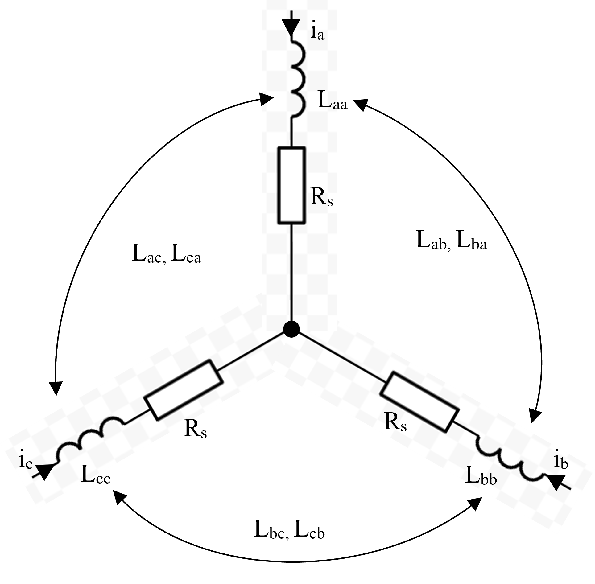
where \omega_r = N_{pp} \Omega is the electrical speed of the rotor field.
Phase inductances (L_{aa}, L_{ab}, L_{ac},..., L_{cc}) are calculated from the rotor reference frame inductance (L_{d}, L_{q}) defined in the property panel as the incremental inductance.
This component will use the lineary interpolated inductance when the current is between the two segmented points.
Electromechanical equations
Electro-magnetic torque:
where \phi_d = L_d i_d and \phi_q = L_q i_q
Mechanical rotational speed \Omega:
Information
The inductance table columns represent q-axis current and its rows represent d-axis current. Both axes must be sorted in ascending order and match the table dimensions. A constant table is supported only when both axes contain exactly one point. Inductance values must be finite and strictly positive.
Library
Electrical > Motors
Parameters
| Property | Display Name | Parameter Type | Description |
|---|---|---|---|
| Rs | Rs - Stator Resistance [Ohm] | DoubleParameter | Stator Winding Resistance [Ohm] |
| Ld | Ld - Direct Axis Inductance [H] | DoubleMatrixParameter | Direct Axis Inductance [H] |
| Lq | Lq - Quadratic Axis Inductance [H] | DoubleMatrixParameter | Quadratic Axis Inductance [H] |
| Ld_2D | Ld - d-axis Inductance Look-up Table | DoubleMatrixParameter | Matrix of output values for d-axis inductance LUT(d,q) |
| Lq_2D | Lq - q-axis Inductance Look-up Table | DoubleMatrixParameter | Matrix of output values for d-axis inductance LUT(d,q) |
| J | J - Rotor Inertia [kg.m²] | DoubleParameter | Rotor Inertia [kg.m²] |
| B | B - Rotor Friction Coefficient [N.m/(rad/s)] | DoubleParameter | Rotor Friction Coefficient [N.m/(rad/s)] |
| InitialSpeed | Rotor Initial Speed [rad/s] | DoubleParameter | Rotor initial speed [ rad/s] |
| InitialCurrent | Initial Current [A] | DoubleArrayParameter | Initial Current Vector [IA IB IC] |
| NPP | NPP - Poles pairs | IntParameter | Number of pole pairs |
| ExposeNeutralPoint | Neutral Point | BoolParameter | Expose Neutral Point (Boolean) |
| Use2DTable | use 2D inductance table | BoolParameter | Use 2D inductance table (Boolean) |
| Id | Id - d-axis Input Current Values | DoubleArrayParameter | Vector of input current (d-axis) |
| Iq | Iq - q-axis Input Current Values | DoubleArrayParameter | Vector of input current (q-axis) |
Pins
| Property | Pin Name | Type | Description |
|---|---|---|---|
| Pin_A | A | Electrical | Phase A (Electrical) |
| Pin_B | B | Electrical | Phase B (Electrical) |
| Pin_C | C | Electrical | Phase C (Electrical) |
| Pin_R | R | RotationalMechanical | Rotor (Rotational Mechanical) |
| Pin_Angle | Angle | ControlOut | Rotor Angle in radians, electrical angle (Control) |
Default Size
| Width | Height |
|---|---|
| 8 | 8 |