Control / Math / Three-Phase PLL
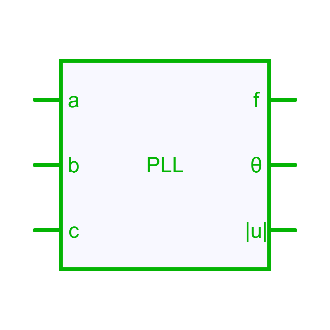
Description
Three-phase Phase-Locked Loop (PLL).
Description
The three-phase Phase Locked Loop (PLL) proposes an estimation of the three-phase system frequency, signal amplitude and the phase-angle. This block implements two types of PLL, which are described in Teodorescu et al. 1: a Synchronous Reference Frame (SRF) PLL and a Decoupled Double Reference Frame (DDSRF) PLL. At initialization, the phase angle and magnitude are derived from the input voltage vector when it is nonzero; Initial Angle and Initial Magnitude are used as fallbacks for a zero-voltage input.
Each PLL is composed of three main functions: * a phase detector: generates an output signal that is proportional to the phase difference between the input signal and the signal generated by the PLL itself; this function will change according to the PLL type. * a low-pass filter: currently a PI controller to attenuate high-frequency components and to eliminate the steady-state phase error. * a phase-angle generator: generates a phase-angle signal based on the estimated angular frequency (typically, it is a wrapping integrator).
Synchronous Reference Frame PLL (SRF-PLL)
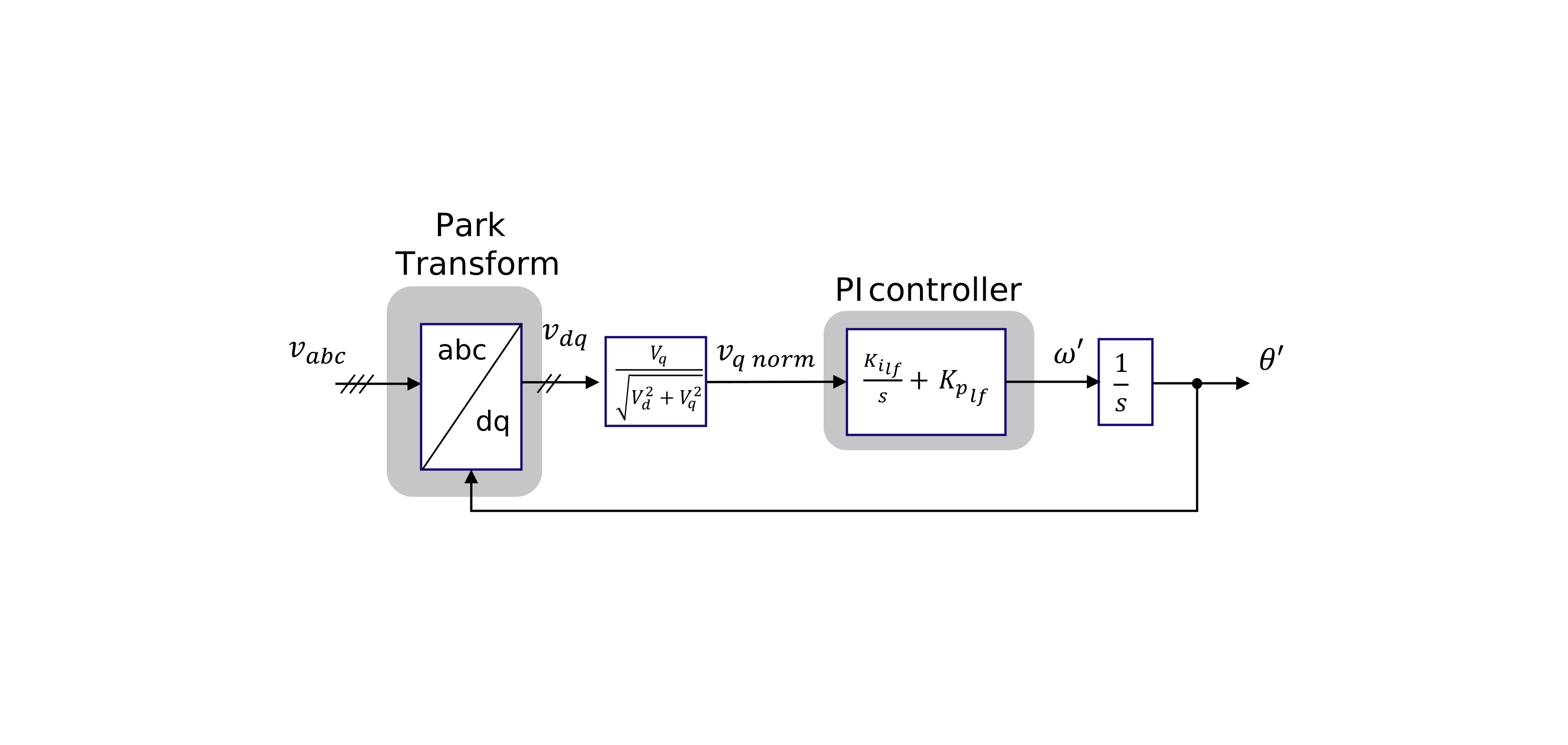
The basic synchronization method in three-phase systems is the Synchronous Reference Frame PLL (SRF-PLL); its structure is shown below.
- The three-phase voltage vector expressed in the natural reference frame is converted into a rotating reference frame through the Park transformation.
- A feedback control loop (low-pass filter) adjusts the instantaneous phase angle by forcing the q-axis component to zero. In steady-state conditions, when the q-axis component is zero, the d-axis component corresponds to the magnitude of the input voltage vector.
This method performs effectively when the grid voltage is balanced and free of harmonic distortion. To reduce the influence of voltage harmonics on the estimation of phase angle and frequency, the PLL bandwidth should be increased. However, under unbalanced grid conditions, an excessively large control bandwidth introduces a double-frequency ripple in the PLL output signals. In this case, a Double Decoupled Reference Frame PLL should be preferred.
Decoupled Double Reference Frame PLL (DDSRF-PLL)
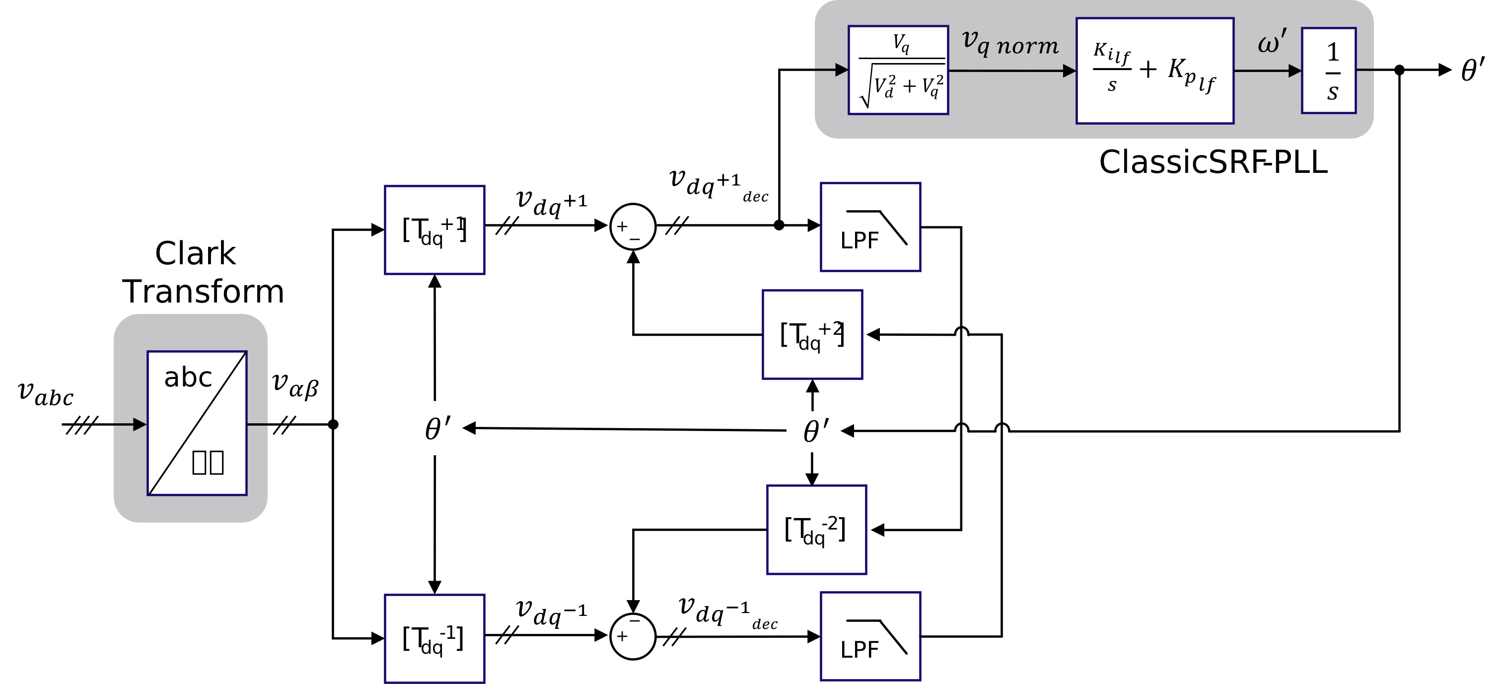
The Decoupled Double Synchronous Reference Frame PLL is well adapted to unbalanced three-phase systems. It uses two synchronous reference frames, rotating with positive and negative synchronous speeds, respectively. These two rotating frames decouple the effect of the negative-sequence component on the dq signals, as shown in the figure below. Since the double-frequency ripple caused by the unbalanced grid condition is avoided, a higher control bandwidth compared to the SRF-PLL can be set.
Controller Design
Two approaches are available to set the loop-filter gains of the PI controller (K_{p_{lf}} and K_{i_{lf}}).
- Auto approach: the parameters are automatically calculated from the nominal frequency f_0 in Hz. The calculation first converts it to the angular frequency \omega_0 = 2\pi f_0 in rad/s.
1 2 3 4 5 6 7 8 9 10 11 12 | |
- Advanced approach: K_{p_{lf}}, K_{i_{lf}} and \omega_f are defined by the user.
Info
The input signal of the PI controller is normalized in the PLL block so the parameters are not required to be scaled.
Important
The unit for phase angle is the radian (rad), and the unit for frequency is the hertz (Hz).
References
Library
Control > Math
Parameters
| Property | Display Name | Parameter Type | Description |
|---|---|---|---|
| Mode | PLL Mode | ThreePhasePLLModeParameter | PLL mode |
| ControllerDesign | Controller Design | PLLControllerDesignParameter | Controller design method |
| Kp_lf | Loop Filter Proportional Gain (Kp_lf) | DoubleParameter | Loop Filter Proportional Gain |
| Ki_lf | Loop Filter Integral Gain (Ki_lf) | DoubleParameter | Loop Filter Integral Gain |
| Wf | Decoupling Filter Pulsation (Wf) | DoubleParameter | DDSRF decoupling filter pulsation [rad/s] |
| InitFreq | Initial Frequency [Hz] | DoubleParameter | Initial Frequency [Hz] |
| InitMag | Initial Magnitude | DoubleParameter | Initial Magnitude |
| InitAngle | Initial Angle [deg] | DoubleParameter | Initial Angle [deg] |
Pins
| Property | Pin Name | Type | Description |
|---|---|---|---|
| A | A | ControlIn | Phase-A input signal |
| B | B | ControlIn | Phase-B input signal |
| C | C | ControlIn | Phase-C input signal |
| Freq | Freq | ControlOut | Estimated Frequency [Hz] |
| Angle | Angle | ControlOut | Estimated Phase-A Angle [rad] |
| Mag | Mag | ControlOut | Estimated phase magnitude |
Default Size
| Width | Height |
|---|---|
| 8 | 8 |
-
R. Teodorescu, M. Liserre, and P. Rodriguez, "Chapter 8 - Grid Synchronization in Three-Phase Power Converters" in Grid Converters for Photovoltaic and Wind Power Systems, John Wiley and Sons, 2010. ↩