JMAG-RT WFSM
Description
Three-phase Wound Field Synchronous Machine(WFSM) block using JMAG-RT model.
JMAG-RT model is a look-up table base motor solution for power electronics/system simulators developed by JSOL Corporation. It solves motor differential equations using parameters from look-up tables created by electromagnetic FEA software JMAG-Designer. JMAG, JMAG-Designer and JMAG-RT are registered trademarks of JSOL Corporation (https://www.jmag-international.com/).
Electrical model and equations
In this block, the below 3-phase base motor differential equation is used to represent the motor dynamics.
where (L_{aa}, L_{ab}, L_{ac},..., L_{ff}) are the inductances depending on the 3-phase current and the rotor DC field current, \phi_f is the field magnetic flux linkage supplied from the DC field winding, and \omega_r is the electrical speed of the rotor field.
Information
In the JMAG-RT WFSM block, the 3-phase base motor differential equation will be solved using a module developed by JSOL Corporation. For details, contact the JSOL Corporation (https://www.jmag-international.com/contact/) or a distributor in your country.
Electromechanical equations
Electro-magnetic torque:
A torque lookup table in the input RTT file will be used for the output torque.
Mechanical rotational speed \Omega:
The following equation is solved to get mechanical rotational speed.
Iron loss modeling
Following iron loss types are available:
- [FundamentalCurrentBaseIronLoss]: Use iron loss tables created using the sinusoidal current in JMAG-Designer.
- [HarmonicsCurrentBaseIronLoss]: Use equivalent iron loss resistance tables to capture the iron loss components due to the carrier frequency and spatial harmonics.
AC copper loss modeling
AC copper loss is a dissipation of electrical energy generated in copper winding due to the skin effect and the proximity effect caused by the high-frequency current. Following AC copper loss types are available:
- [GeometryBaseACCopperLoss]: Use the motor slot geometry information in the JMAG-RT model to calculate the AC Copper loss.
- [UserDefinedACCopperLoss]: Use AC copper loss tables added to JMAG-RT models from CSV files created by the user.
Information
When AC copper loss is not used, the "copper loss" scope outputs only DC copper loss, i.e. a sum of the product of the phase resistance and the squared phase current. When AC copper loss is used, the "copper loss" scope outputs a sum of AC coper loss and DC copper losses
Correction factors
Correction factors are applied to the input motor model in the following manner.
Where \phi is total magnetic flux linkage [wb], K_1 is a correction factor for inductance, K_2 is a correction factor for total magnetic flux linkage, K_3 is a correction factor for torque, K_5 is a correction factor for steel core, N is the original number of turns, N_1 is a new number of turns used to modify the inductance value and total magnetic flux linkage value as a function number of turns, and N_2 is a new number of turns used to modify the current used to refer to the look-up tables.
Thermal modeling
In order to represent the temperature dependency of the motor characteristics, JMAG-RT models the phase resistance and the magnet flux in the following manner.
Where \alpha is temperature correction factor for winding [ppm / ^\circ C ],
T_{cnow} is the coil temperature at the current step [^\circ C ],
T_{cbase} is the base coil temperature for windings[^\circ C ]
Information
Temperature correction factors and base temperatures are defined when the JMAG-RT model is created and stored in the JMAG-RT model. The temperature at the winding thermal port is the current temperature in the above equation. The losses dissipated in the machine at every step are available as the core losses and copper losses from the core thermal port and the winding thermal port respectively.
Library
Electrical > Motors
Parameters
| Property | Display Name | Parameter Type | Description |
|---|---|---|---|
| RttFilePath | RTT File Path | FilePathParameter | Path to the RTT library (String) |
| J | J - Rotor Inertia [kg.m²] | DoubleParameter | Rotor Inertia [kg.m²] |
| B | B - Rotor Friction Coefficient [N.m/(rad/s)] | DoubleParameter | Rotor Friction Coefficient [N.m/(rad/s)] |
| InitialSpeed | Rotor Initial Speed [rad/s] | DoubleParameter | Rotor initial speed [ rad/s] |
| ConnectionType | JMAG-RT Connection Type | JMAGRT_ConnectionParameter | Connection Type (Star or Delta) |
| Rs | Rs - Stator Phase Resistance [Ohm] | DoubleParameter | Phase resistance [Ohm] |
| Rf | Rf - DC Field Resistance [Ohm] | DoubleParameter | Field resistance [Ohm] |
| Offset | Angle difference from A-phase to d-axis [Mech. deg] | DoubleParameter | Angle to align the rotor magnet to A-phase [Mech.deg] |
| AverageLossCalcFreq | AverageLossCalcFreq - Average Loss Calcualtion Frequency [Hz] | DoubleParameter | Average Loss Calcualtion Frequency [Hz] |
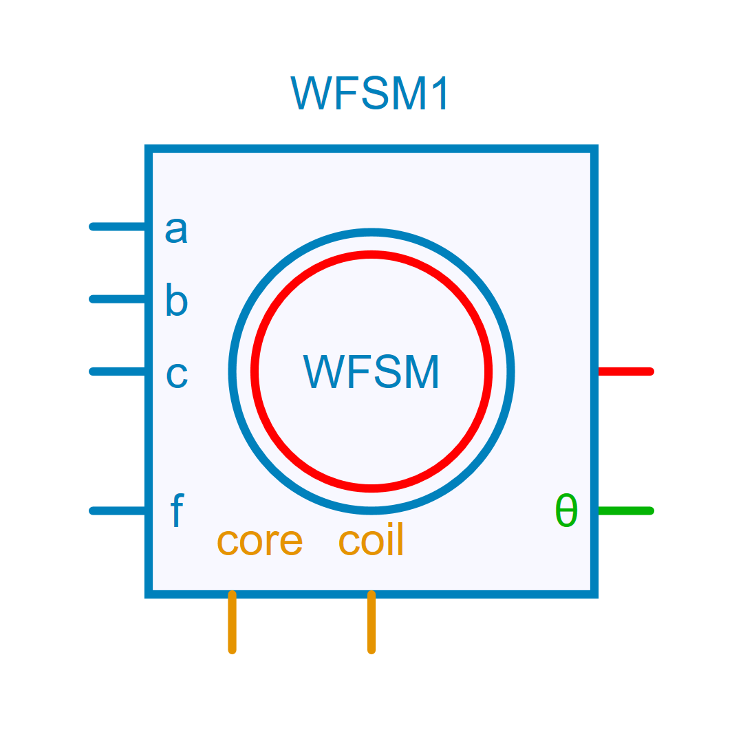
Pins
| Property | Pin Name | Type | Description |
|---|---|---|---|
| Pin_A | A | Electrical | Phase A (Electrical) |
| Pin_B | B | Electrical | Phase B (Electrical) |
| Pin_C | C | Electrical | Phase C (Electrical) |
| Pin_F | F | Electrical | Rotor DC Field (Electrical) |
| Pin_R | R | RotationalMechanical | Rotor (Rotational Mechanical) |
| Pin_Angle | Angle | ControlOut | Rotor Angle in radians, mechanical angle (Control) |
| Pin_Pcore | Core | Thermal | Core (Thermal) |
| Pin_Pwinding | Winding | Thermal | Winding (Thermal) |
Default Size
| Width | Height |
|---|---|
| 8 | 8 |