PLL
Description
Single-phase Phase-Locked Loop (PLL)
Description
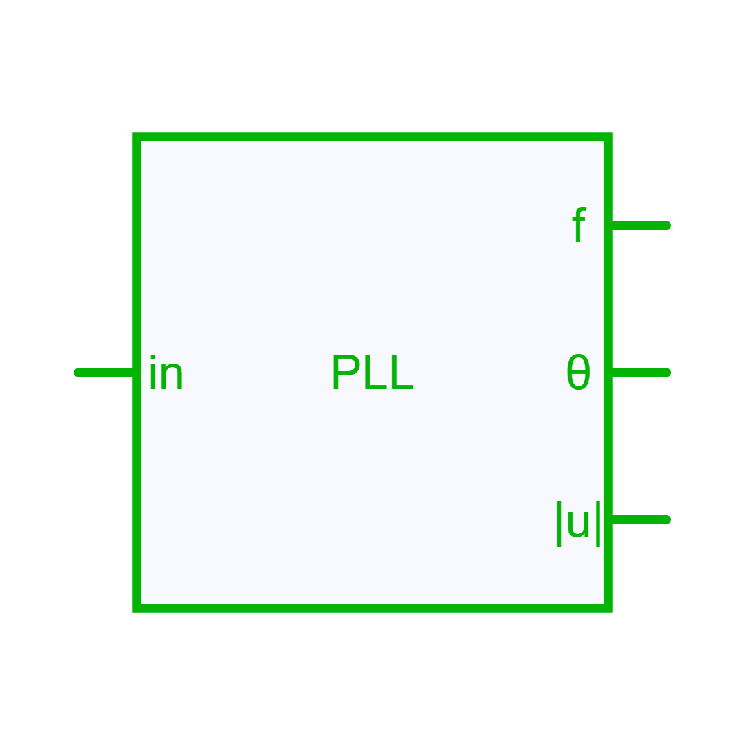
The single-phase Phase Locked Loop (PLL) proposes an estimation of the input signal frequency, signal amplitude and the phase-angle. This block implements two types of PLL which are described in Teoderescu et al.[^1]: an Enhanced PLL and a Second Order Generalized(SOGI) PLL. Each PLL can be derived by three main functions:
- a phase detector: generates an output signal that is proportional to the phase difference between the input signal and the signal generated by the PLL itself; this function will change according to the PLL type.
- a low-pass filter : currently a PI controller to attenuate high-frequency components and to eliminate the steady-state phase-error.
- a phase-angle generator: generates a phase-angle signal based on the estimated angular frequency (typically, it is a wrapping integrator).
Enhanced PLL
As shown below, the performance of the basic PLL implementation is enhanced with an Adaptative Noise Canceling(ANC) system which is an Adaptative Notch Filter(ANF).

The output of the ANF becomes equal to zero as the frequency and phase-angle of the reference signal generated by the VCO, x = cos(θ′), match those of the input signal v. As a result, signal oscillations at the output of the multiplier PD are completely cancelled out and the input signal phase - angle is accurately estimated by the basic PLL structure.
Second Order Generalized (SOGI) PLL
As shown below, the adaptative filter is implemented by a system named * Second Order Generalized Integrator - Quadrature Signal Generator(SOGI-QSG)* which allows the generation of two quadrature signals(V_{\alpha}, V_{\beta }) sent to a park transform block to detect the phase.

This system has a double feedback loop; i.e. the frequency/phase generator provides both the phase-angle to the Park transform and the central frequency to the SOGI-QSG. From the structure given in above figure the following relevant transfer functions of the structure can be derived:
SOGI anti-windup
By default, the SOGI PLL enables a low-frequency saturation at 0.4 f_0 and an anti-windup correction on the loop-filter integrator. This prevents the estimated frequency from collapsing during severe transients or large phase errors. Set Disable Anti-Windup only when the basic SOGI block diagram is required; in that case, the low-frequency saturation and the anti-windup correction are both removed.
Controller Design
Two approaches to set the gains of the phase detector (K_{i_{pd}}) and of the loop filter which is a PI controller (K_{p_{lf}} and K_{i_{lf}}).
- Auto approach: the parameters are automatically calculated [^2] to get a settling time (ts) of approximately 3 / f_0 where f_0 is the frequency defined by the user.
ts = 3 / fo;         // Settling Time
xsi = 1 / sqrt(2);   // Damping factor
Kp_lf = 9.2 / ts;
Ti_lf = ts * xsi^2 / 2.3;
Ki_lf = Kp_lf / Ti_lf;
if type == "Enhanced" {
   Ki_pd = Kp_lf; // Enhanced PLL
   }
else
   {
   Ki_pd = sqrt(2); // SOGI PLL
   }
- Advanced approach: K_{i_{pd}}, K_{p_{lf}} and K_{i_{lf}} are defined by the user.
Info
The input signal is normalized in the PLL block so the parameters are not required to be scaled.
Important
The unit for phase-angle is the radian (rad) and the unit for the frequency is the Hertz (Hz).
References
[1]: R. Teodorescu, M. Liserre, and P. Rodriguez, "Chapter 4 – Grid Synchronization in Single-Phase Power Converters" in Grid Converters for Photovoltaic and Wind Power Systems, John Wiley and Sons, 2011.
[2]: Y. Yang, K. Zhou Chapter 4 - Modeling and Control of Single-Phase AC/DC Converters in Control of Power Electronic Converters and Systems Vol 1, Science Direct, 2018.
Library
Control > Math
Parameters
| Property | Display Name | Parameter Type | Description |
|---|---|---|---|
| Mode | PLL Mode | PLLModeParameter | PLL mode |
| ControllerDesign | Controller Design | PLLControllerDesignParameter | Controller design method |
| DisableAntiWindup | Disable Anti-Windup | BoolParameter | Disables the low-frequency saturation and anti-windup correction in SOGI mode. |
| Ki_pd | Amplitude Integral Gain (Ki_pd) | DoubleParameter | Amplitude Integral Gain |
| Kp_lf | Loop Filter Proportional Gain (Kp_lf) | DoubleParameter | Loop Filter Proportional Gain |
| Ki_lf | Loop Filter Integral Gain (Ki_lf) | DoubleParameter | Loop Filter Integral Gain |
| InitFreq | Initial Frequency [Hz] | DoubleParameter | Initial Frequency [Hz] |
| InitAngle | Initial Angle [deg] | DoubleParameter | Initial Angle [deg] |
| InitMag | Initial Magnitude | DoubleParameter | Initial Magnitude |
Pins
| Property | Pin Name | Type | Description |
|---|---|---|---|
| In | In | ControlIn | Input signal |
| Freq | Freq | ControlOut | Estimated Frequency [Hz] |
| Angle | Angle | ControlOut | Estimated Phase Angle [rad] |
| Mag | Mag | ControlOut | Estimated Magnitude |
Default Size
| Width | Height |
|---|---|
| 8 | 8 |