Brushless DC Motor (BLDC)
Description
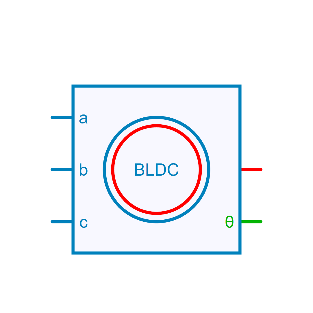
Brushless DC Motor (BLDC)
This model represents a brushless DC (BLDC) motor with trapezoidal back electromotive force (EMF). During motoring operation, the torque and speed share the same sign. The rotor angle is defined as the angle between the a‑phase and the d‑axis, with its reference position set where the negative d‑axis current aligns with the positive a‑phase current.
Magnetic saturation is modeled using a piecewise‑linear approximation of the direct‑ and quadrature‑axis inductances. The stator windings are connected in a star configuration. To access the neutral‑point terminal, enable the Neutral Point option in the property panel.
Electrical model and equations
where v_a, v_b, and v_c are phase voltages. Phase inductances (L_{aa}, L_{ab}, L_{ac},..., L_{cc}) are computed from the incremental inductances in the rotor reference frame (L_{d}, L_{q}) specified in the property panel. When the phase currents fall between two defined saturation points, the model uses linearly interpolated inductance values.
Back EMF e_a, e_b, and e_c use trapezoidal waveforms:
where \omega_r = N_{pp} \Omega is the electrical speed of the rotor field, and \phi_m = \frac{K_e}{N_{pp}} is the permanent magnet flux linkage. f_a(\theta_r), f_b(\theta_r), and f_c(\theta_r) are unit trapezoidal functions of the rotor position.
Electromechanical equations
Electro-magnetic torque:
Mechanical rotational speed \Omega:
Reference
[1] Modeling and control of a brushless DC motor. MTech thesis, S. Rambabu, Department of Electrical Engineering National Institute of Technology Rourkela, 2007 https://core.ac.uk/download/pdf/53188902.pdf
[2] Simulation of BLDC Motor Speed PI Control in Simulink, Malcolm's Technical Blog Embedded, electronics, and other stuff https://malichao.wordpress.com/2015/11/18/simulation-of-bldc-motor-speed-pi-control-in-simulink/
Library
Electrical > Motors
Parameters
| Property | Display Name | Parameter Type | Description |
|---|---|---|---|
| Rs | Rs - Stator Resistance [Ohm] | DoubleParameter | Stator Winding Resistance [Ohm] |
| Ld | Ld - Direct Axis Inductance [H] | DoubleMatrixParameter | Direct Axis Inductance [H] |
| Lq | Lq - Quadratic Axis Inductance [H] | DoubleMatrixParameter | Quadratic Axis Inductance [H] |
| Ke | Ke - Back-EMF Constant [V/(rad/sec)] | DoubleParameter | Back-EMF Constant |
| J | J - Rotor Inertia [kg.m²] | DoubleParameter | Rotor Inertia [kg.m²] |
| B | B - Rotor Friction Coefficient [N.m/(rad/s)] | DoubleParameter | Rotor Friction Coefficient [N.m/(rad/s)] |
| InitialSpeed | Rotor Initial Speed [rad/s] | DoubleParameter | Rotor initial speed [ rad/s] |
| InitialCurrent | Initial Current [A] | DoubleArrayParameter | Initial Current Vector [IA IB IC] |
| NPP | NPP - Poles pairs | IntParameter | Number of pole pairs |
| ExposeNeutralPoint | Neutral Point | BoolParameter | Expose Neutral Point (Boolean) |
Pins
| Property | Pin Name | Type | Description |
|---|---|---|---|
| Pin_A | A | Electrical | Phase A (Electrical) |
| Pin_B | B | Electrical | Phase B (Electrical) |
| Pin_C | C | Electrical | Phase C (Electrical) |
| Pin_R | R | RotationalMechanical | Rotor (Rotational Mechanical) |
| Pin_Angle | Angle | ControlOut | Rotor Angle in radians, electrical angle (Control) |
Default Size
| Width | Height |
|---|---|
| 8 | 8 |