PLL
Description
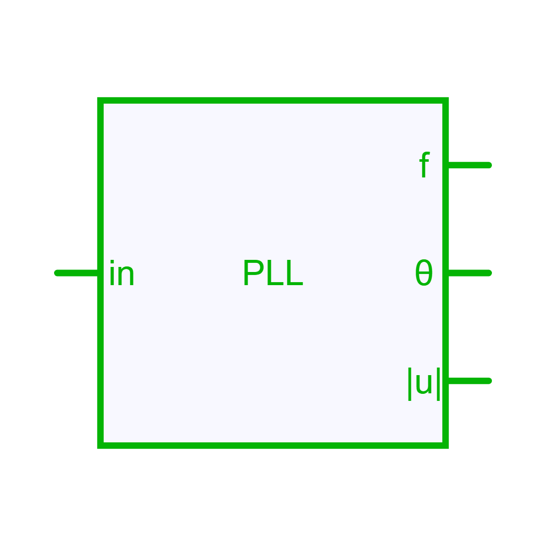
Single-phase Phase-Locked Loop (PLL)
Description
The single-phase Phase Locked Loop (PLL) proposes an estimation of the input signal frequency, signal amplitude and the phase-angle.
This block implements an Enhanced PLL described in Teoderescu et al.[1]
As shown below, the performance of the basic PLL implementation is enhanced with an Adaptative Noise Canceling (ANC) system which is an Adaptative Notch Filter (ANF).

The output of the ANF becomes equal to zero as the frequency and phase-angle of the reference signal generated by the VCO, x = cos(θ′), match those of the input signal v. As a result, signal oscillations at the output of the multiplier PD are completely cancelled out and the input signal phase-angle is accurately estimated by the basic PLL structure.
Controller Design
Two approaches to set the gains of the phase detector (K_{i_{pd}}) and of the loop filter which is a PI controller (K_{p_{lf}} and K_{i_{lf}}).
- Auto approach: the parameters are automatically calculated [2] to get a settling time (ts) of approximately 3 / f_0 where f_0 is the frequency defined by the user.
ts = 3 / fo;         // Settling Time
xsi = 1 / sqrt(2);   // Damping factor
Kp_lf = 9.2 / ts;
Ti_lf = ts * xsi^2 / 2.3;
Ki_lf = Kp_lf / Ti_lf;
Ki_pd = Kp_lf;
- Advanced approach: K_{i_{pd}}, K_{p_{lf}} and K_{i_{lf}} are defined by the user.
Info
The input signal is normalized in the PLL block so the parameters are not required to be scaled.
Important
The unit for phase-angle is the radian (rad) and the unit for the frequency is the Hertz (Hz).
References
[1]: R. Teodorescu, M. Liserre, and P. Rodriguez, "Chapter 4 – Grid Synchronization in Single-Phase Power Converters" in Grid Converters for Photovoltaic and Wind Power Systems, John Wiley and Sons, 2011. [2]: Y. Yang, K. Zhou Chapter 4 - Modeling and Control of Single-Phase AC/DC Converters in Control of Power Electronic Converters and Systems Vol 1, Science Direct, 2018.
Library
Control > Math
Pins
| Name | Description |
|---|---|
| In | Input signal |
| Freq | Estimated Frequency [Hz] |
| Angle | Estimated Phase Angle [rad] |
| Mag | Estimated Magnitude |
Parameters
| Name | Description |
|---|---|
| SamplingTime | -none or 0: No sampling. The system will be solved in the Newton loop (default). -auto: Inherit the sampling time of its source device. -Sampling Period: defined in seconds. |